Pipelines in the various sectors that use process equipment require timely maintenance, repair, refurbishment, and even the necessary modification; that companies might require to increase plant productivity in complex exercises that are a masterpiece conglomeration of fluid dynamics, design engineering, logistics, personnel management and use of innovative equipment.
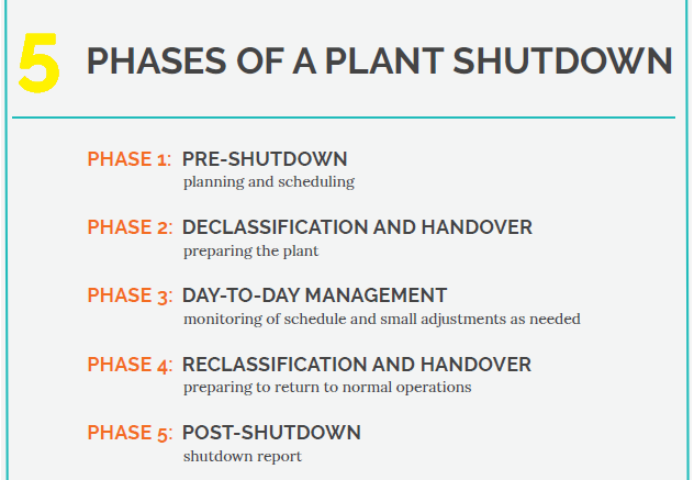
These exercises are called shutdowns, and they require immense planning, engineers keep them well-defined with a limited scope. The reason for keeping their duration limited is to reduce the losses in productivity caused by a drop in the product output of the plant. While reducing shutdown time, experienced crews and reliable machines must carry out the needed process with safety in mind considering potentially explosive environments.
Some Machining Techniques involve redirecting pipeline working fluid without stopping the flow of the fluid in a live pipeline as well, thus keeping productivity largely intact.
There are several methods of making these pipes and many more of cutting, welding, bolting, bending & connecting them. We shall focus on the methods involving In Situ Machining using highly mobile and flexible cutting techniques and the machinery that makes the same possible along with other processes that allow for pipeline modification and repair without bringing the pipeline or its section to any plant or machining site specifically.
Types of In-Situ Machining Methods:
- Pipeline Hot Tapping and Line Stopping
- Pipeline Water Jet Cutting
- Pipe Cutting & Bevelling
- Pipe Flange Facing
A) Pipeline Hot Tapping & Line Stopping:
Productivity is critical for maintaining profitability for the large economies of scale plants that, to provide an example: refine crude oil into various petrochemical products. Various pipeline fluid mediums such as steam, flare gas, crude oil, water, etc. require careful handling while the pipelines carrying them are drilled into and the flow is redirected to a conduit and then to its original destination.
A main pipeline called a ‘mother pipeline’ is the one that has the flowing fluid. The pipes, to which the mother pipeline could be connected are called ’branch pipelines’.
The purpose of Conducting Hot Tapping would be amongst the following:
- To remove a damaged or rusted section of pipes
- To create a conduit for the fluid to another pipeline or avoid a certain area and reconnect to the same pipeline.
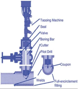
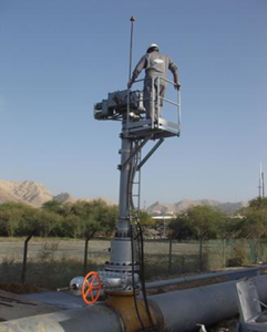
The hot-tapping machine shown below has the following components:
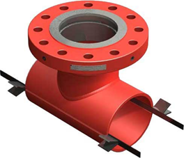
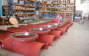
- Full Encirclement Fitting or Joints – usually have a pipe flange attached to them.
- Valve housing – Connected by bolts on the flange
- Tapping Machine – This is the actual element that shall perform the cutting, it has a drive component or motor that is electrically or hydraulically driven and rotates the Boring Bar that moves back and forth using a hydraulic mechanism. Here the feed and speed can be controlled.
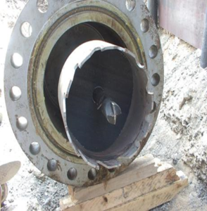
- Cutter – The Cutting Element has a Pilot Drill which cuts and retrieves a cut section of the pipe called a coupon with a set of prongs that stop the cut section from falling back into the pipe.
The process involves the following steps:
a) Welding or Bolting the appropriate Joints on the Pipes to be hot-tapped in minimum number to carry out to the line stopping after hot tapping is conducted.
Examples include: Bolted or Welded Split Tee, Weld-O-Let, and Reinforcement (RF) pads
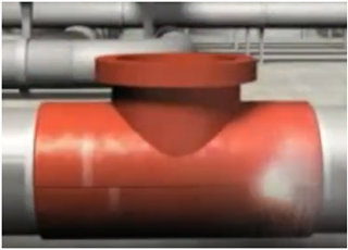
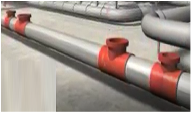
b) Bolting of the Valve housing onto the joint is carried out which shall allow the tapping machine to be mounted on the same with smaller valves being fastened on the joints and correct measurements are made for the fittings.
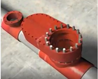
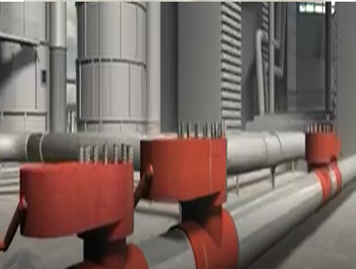
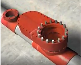
c) The Tapping Machine is mounted on the valve housing and the tapping is initiated using manual machines for the smaller taps and larger machines for the main taps
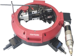
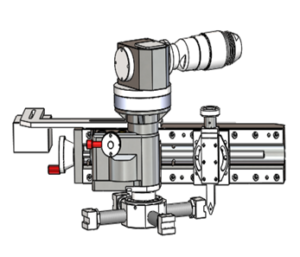
d. Now that both the taps are opened the pipe sections are connected, and the conduit is inserted and bolted on the valve housings of both, hence continuing the flow of the working fluid.
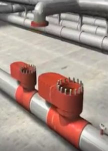
e. Further, the Line Stopping Machine is attached to the valve housing the Stopple is extended into the pipe and the flow is obstructed. In Some cases, an inflatable bag is used to stop the effervescent fumes from escaping to prevent an explosive environment or asphyxiating gasses from harming workmen or stopping their work. The excess pressure is released from the pipe which is now effectively cordoned off using line stopples.
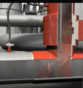
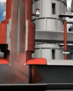
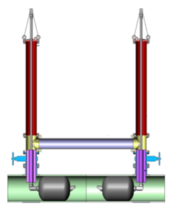
f. The Damaged or rusted section of the pipe or the desired pipeline modification is initiated.
The evacuated pipeline allows for safe working with the isolated section and a new pipe section can thus be added without loss of productivity.
g. The Line Stopple is now Withdrawn behind the valve gate and the excess gas (if any) is released. The fluid is now free to move through the pipe and hot tapping/line stopping machines are now withdrawn.
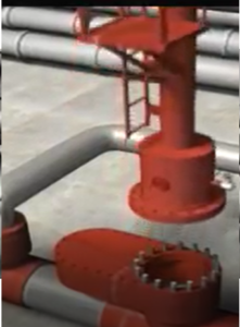
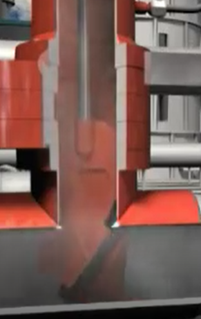
being withdrawn
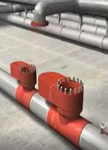
h. The Completion Flanges or blanks are now bolted and the welded fittings/joints are left in place, if the joints are bolted then they are withdrawn.
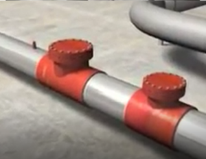
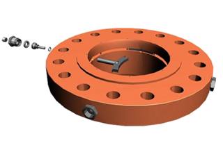
Completion Flanges are placed ensuring leakages at high pressure are unlikely
Various Orientations wherein the Hot Tapping and Line Stopping process could be carried out include the following:
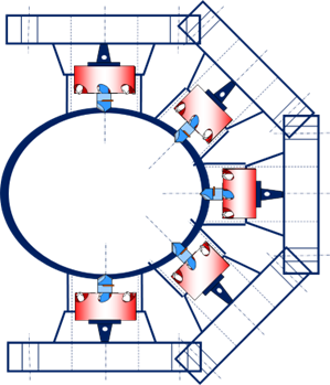
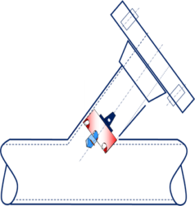
In Addition to Pipeline Hot Tapping /Line Stopping on Land, it can also be performed on Pipelines underwater.
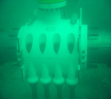
Special Underwater Sealed Valve Gates and Fittings and Joints ensure leak-free hot tapping/ line stopping material
B) Pipeline Water Jet Cutting:
In Explosive Environments the use of conventional pipe cutting techniques and machines is hazardous. To carry out In Situ Maintenance, Repair, and Overhaul of pipes thus calls for a truly spark-free operation. Water concentrated with high pressures has been used for cutting wood since the late 20th Century. Since then the process has evolved to also include metals of large thickness.
Water is pressurized using specialized pumps and the water is mixed with powdered garnet or other abrasives. This abrasive mixed slurry is released out of a narrow nozzle measuring 0.1 mm to 0.5 mm with very high pressure measuring at 1000s of Bars of Pressure. The Accuracy of this process in some cases even surpasses Laser Jet Cutting due to lack of heat distortion.
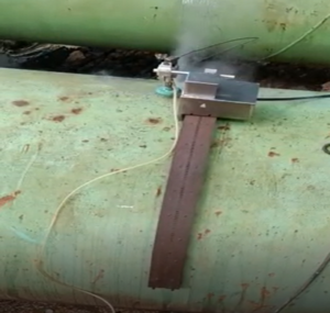
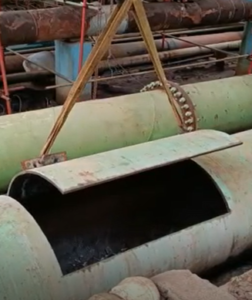
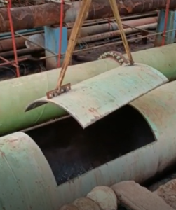
Pipeline Being Cut using Guide Rail and Water Jet cutting method
Thus to elaborate, this process has the following machinery & equipment involved.
- Water Tank and Pump
- Intensifier Pump
- Pneumatic Abrasive Delivery Feeder
- Magnet Abrasive Tank
- Magnetic carriage for the Waterjet Nozzle and Regulator
- Remote Operation Pendant
- High-Pressure Pipe to connect intensifier pump and tools


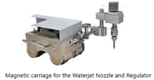


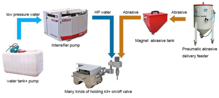
The Use of High-Pressure Pumps and pneumatically pressurized abrasive material to mix it with water. The Slurry is then jetted out of a fine nozzle to cause material removal on the workpiece.
C) Pipe Cutting and Beveling Machines:
A Quick, Reliable, and relatively Cost-effective method of Pipe Cutting is a frequent need in Oil and Gas plants and connecting Pipelines from Oil Wells to Distributors and everything in between. The ability to machine, isolate, and prepare pipes for welding without moving them to a different location entirely is highly desirable.

A portable & lightweight machine that is sturdy is industry standard. The Insitu machining would be incomplete without these machines.
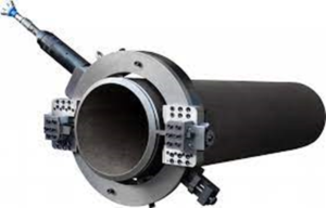
These machines are mounted on the Internal Diameter or the External Diameter of the Pipe and the locator pads are fastened against the pipe according to its ovality. A point to keep in mind is that the seamless or seamed pipes are never fully uniform in thickness or in their roundness.
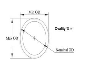
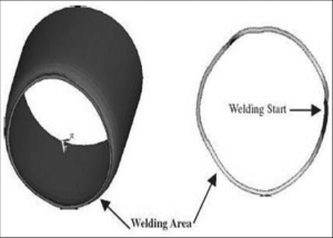
Cutting pipes with Conventional Pipe Cutting Methods is hazardous in explosive environments, thus being able to utilize safer drive methods such as pneumatic pressure is preferable.
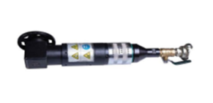
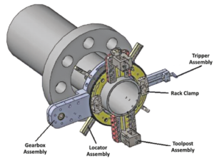
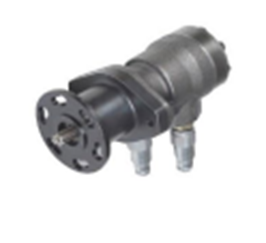
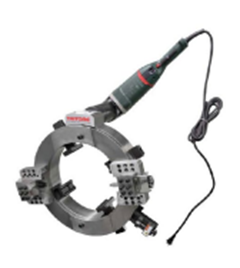
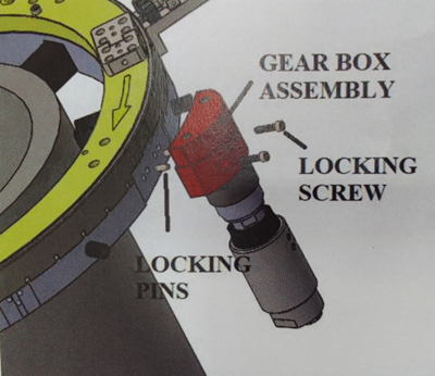
An Air Operated Motor That Drives the Rotating Ring on the Pipe Cutting Machine. It is mounted on the gearbox assembly on the machine.
Risk Assessment and Hazard Mitigation:
- Machine Tools are specifically designed to perform precise material removal operations.
- Stationary Machine Tools include lathes and milling machines and are typically found in a machine shop. They are mounted in fixed locations during operation and are considered to be a complete, self-contained machine. Stationary Machine Tools achieve the rigidity needed to accomplish material removal operations from the structure that is an integral part of the machine tool.
- In contrast, Portable Machine Tools are designed for on-site machining applications. They typically attach directly to the workpiece itself, or to an adjacent structure, and achieve their rigidity from the structure to which it is attached to become one complete machine during the material removal process.
- To achieve the intended results and to promote safety, the operator must understand and follow the design intent, setup, and operation practices that are unique to portable machine tools.
The operator must perform an overall review and on-site risk assessment of the intended application, Due to the unique nature of portable machining applications, identifying one or more hazards that must be addressed is typical

To Elaborate further on how these machines work:
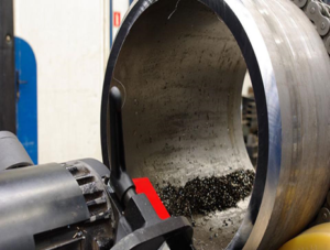
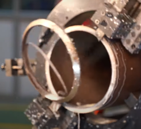
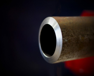
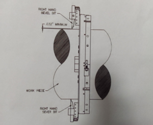
Here, we shall assess a portable pipe-cutting machine/lathe that can sever and bevel pipelines simultaneously in the pipeline. These machines can form any bevel angle as they cut. These tools are portable machines that are strong enough to cut and bevel heavy wall pipes and rigid enough to reface worn flanges. The frame is split for easy installation and the tool bits automatically feed into the workpiece with each rotation of the lathe to ensure precision machining.
Machining Function & Ability:
- Sever In-line Pipe
- Sever and Bevel In Line Pipe
- Sever and Double Bevel In Line Pipe
- Socket Weld Removal
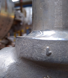
Components of the Pipe Cutting and Beveling Machine:
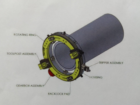
- Hosing
- Rotating Rack Ring Assembly
- Gear Box Drive Assembly
- Bearings
- Tools Post Slide Assembly
- Tripper Assembly
- Universal Locator Assembly
Housing: An Aluminum Split Ring Housing, Connected with Swing Bolts, that is capable of being dismantled for installation on in-line piping. The housing has bearing mountings for the rotating cutting head, a mount for the drive motor for drive motor assembly, and locator pockets.
Rotating Rack Ring Assembly: Made of Alloy Steel, this split ring assembly, connected by the gear clamps, will align with the split lines of the housing when the machine is split into halves. The Cutting head assembly has gear teeth on the outside diameter of the cutting head and mounting locations for the slide assemblies. An internal bearing race allows the cutting head to rotate about the housing.
Gear Box Drive Assembly: Mounted to the housing and arranged with a pinion gear on a shaft. The motor mounting bracket is designed to accept the reaction torque generated by the drive motor. Alignment keys are used to guarantee perpendicularity between the motor and the cutting head.
Bearings: The Cutting head assembly runs on bearings that provide for axial and radial force reactions. The bearings are adjustable to compensate for normal wear.
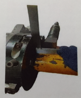
Tool Post Slide Assembly: The Slide Assembly is designed to hold the cutting tool (tool bit). The slide assembly has adjustable jibs and also contains a feed screw assembly, which is used to feed the tool bit into the workpiece. The slide assemblies are bolted to the face of the machine assembly and can be moved in increments.
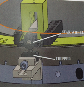
Tripper Assembly: The Tripper assembly is designed to hold the tripper pin. The Tripper pin is used to turn the star wheel on the feed screw assembly, which feeds the tool bit into the workpiece. The tripper assembly is bolted to the OD of the housing. There are four different types of mounting locations that allow for more flexibility in the machine mounting.
Universal Locator Assembly: The alloy steel machine uses adjustable locator assemblies with some travel range. Turning sert screws located on the outside of the housing actuated the adjustable locators. Locator extensions are required to mount on a smaller diameter pipe. Not Applicable in the case of universal locator assembly.
For a better understanding watch the below video by clicking on the link:
Let us now understand the steps to operate these machines in detail:
Prep work:
- Clear all the obstructions and non-essential personnel and equipment
- Check that the area where the control/observation area of the machine is not located in the path of the hot flying metal chips
- Mount the machine securely to the workpiece.
- Make sure that the pneumatic/ air hoses are routed and secured in a manner that ensures that no trips over them, and they do not entangle with other equipment, in the path of the hot metal chips. ensure clearance to make sure damage to other equipment is minimal in case the air hose fails.
- Check the tools for their condition and sharpness
- Ensure all hand tools loose parts and equipment are removed from the area of operations.
Installation of the machine:
a)First the Joining Machine halves are completed using locator pads c) Setting the tools bits
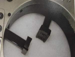
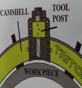
b) Squaring & Centering d) Motor Installation
Machine Operation:
Now that the machine and the tool bit have been properly secured on the pipe. The cutting operation can be initiated.
- The Cutting Operation is a continuous operation until stopped by the operator stops the cutting feed during rotation, lifts the tripper handle, and let the machine rotate a few times to clear the tool bit. Turn off the power to stop the machine rotation. Letting the tool bit clear will prevent tool damage and gouging.
- Engage the tripper pin by pushing down on the tripper handle. If Chatter or vibrations occur, reduce cutting RPM. If the tool bits chip or become dull, replace them immediately with sharp bits. Do not sharpen the tool bits. They must be sent to the factory for regrinding to maintain proper relief angles. Damage to the machine could occur. Use coolant during the cutting operation to reduce friction on the cutting edge.
- Stop the machine when the severing is complete. Back put the tool blocks with the star wheel wrench to the full position.
- Follow tool bit setup procedures replacing both sever bits either left hand or right hand sever, bevel combinations. Back the bevel nit above the server bit and follow the procedure above, until the pipe is severed and beveled.
Machine Removal:
- Retract Tool Slide
- Disconnect the power source and remove the motor
- Loosen the expanding blocks that hold the split frame in position.
- Remove the split frame from the pipe.
D) Pipe Flange Facing: Apart from Sockets and Spigot Joints which are very common in concrete pipes, large metal pipes use flanges to provide easier customisation & maintenance access and also suitability for a wide range of volumes, temperatures, and pressures of various chemicals whether they are gasses or liquids.
A Flange is an effective and proven mechanical member of a piping system. Its primary function is to allow access for inspection, cleaning, maintenance, repair, and even modification of the system. These are either welded or screwed into the primary piping system. Operators fasten Flanged joints by bolting together two flanges with a gasket to provide a seal. Flanges allow us to install components in the piping system.
Several Flange types are used primarily in the Petrochemical and Chemical Industry Some of them are:- Welding neck flange, Slip-on flange, Socket Weld Flange, Lap joint flange, Threaded Flange, and Blinded Flange. Manufacturers make these flanges using stainless steel, cast iron, aluminum, brass, bronze, plastic, etc., but the most used material is forged carbon steel and has machined surfaces.
The interfaces between these flanges connecting two pipes are called flange faces. A flange face is its sealing face.
Here are shown below bolted joints on the blade of the flange and the flange facing required to make sure that the gaskets used to connect and ensure leak-free joints have a proper seat on them.
We shall now focus on the flange mating interfaces and the types of surface finish.
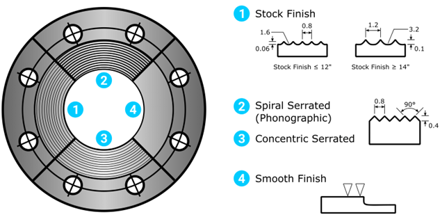
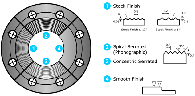
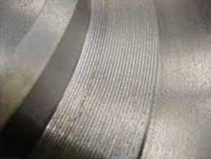
Flange surface faces can be classified as smooth (also called ‘flat’ or ‘plain’) or serrated. Smooth faces appear visually ‘smooth’ and have no visual tool markings. Serrated faces have some form of tool markings on the flange face.
Flange assembly must be mated and tightened to the required torque in order to seal correctly.
High-temperature and high-pressure system flanges use a serrated sealing surface or a metal gasket. Low-temperature and low-pressure system flanges may use a smooth flange face surface and soft gaskets.
Smooth Flanges:
Smooth Flange surfaces have a finish that is featureless and have a smooth flange surface on the entire flange face. Seal integrity is determined by many factors, including -but not limited to:-
- Gasket sealing material.
- Gasket design.
- Flange construction material.
- Service conditions (temperature, pressure, etc.).
- Following the correct bolting procedure.
Serrated Flange Surface:
Serrated flange surfaces consist of concentric circular grooves or a continuous spiral groove (also known as ‘phonographic’) machined onto the flange sealing surface. Serrated flange surfaces use non-metallic (soft) and semi-metallic gaskets.
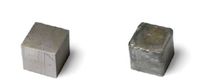
The image below shows the two serration types. The spiral serration in the image is exaggerated because it is sometimes difficult to see the spiral shape on a real flange, due to the closeness of the serrations.

Serrations provide more resistance when mating with gaskets, which ultimately leads to a lower probability of leakage as the likelihood of gasket dislocation (un-sealing) is reduced; this is true even when less sealing pressure (bolt torqueing) is applied.
Now to focus on the machines that make these machining patterns:
There are predominantly two types of these machines which can be distinguished by the mounting type:
These machines depending on the space available and the restrictions around the pipe are selected. The Machines can perform tasks such as the following:
- Flange Facing and Bevelling
- Machine Seal Grooves
- Make Serrated Finishes (Phonographic)
- Continuous Groove Facing Feeds
The machines must be necessarily portable to be transported to the site for the machining to begin and must be sturdy enough to face the flange accurately.
* will we now understand how these machines work.
The Flange flange machine is a three-piece mounting system that makes setup and alignment of this machine quick and easy. It is lightweight and portable. This machine allows you to face, bevel, turn pipe, valve, and pump flanges with ease.
The flange-facing machine should be aligned with the internal diameter correctly with the necessary steps and the cutting tool should be adjusted according to the cut desired.
The end result is that the gasket is mounted without slipping from the flange face.
A few safety instructions before operations can begin:
- Safety Protective Equipment must be worn at all times during machine operation and the clamping machine must be locked properly. Adjust the workpiece at low speed but not at high speed. Stay away from rotating equipment to prevent injury. Electrical wires should be kept far away from high temperature, oily or sharp places.
- When there is a malfunction or abnormal sound, the power supply shall be shut down immediately through a remote control and then to start checking and repairing. Do not let the machine operate without anyone watching. Operators can only leave after the machine stops and make sure the power supply is switched off and the transmission system is in a free position. Do not run the machine beyond its capacity.
- Oil stain and iron dust shall be removed after work is done. And anti-corrosive oil shall be put on the cutting arm and main axis.
Conclusion:
The practice of In Situ Machining is an important fixture in the world of Pipeline Maintenance, Overhaul, and Repair. The tools and machines mentioned here are indispensable to this task. Machining pipes to prepare them for welding and customizing pipelines to add capacity to plants in the same location where they are supposed to be installed is a boon that reduces downtime and increases plant productivity. This in return makes our lives better as the amenities continue to flow when pipes are joined for sure.
ECOSYSTEM
Positive growth.
Nature, in the common sense, refers to essences unchanged by man; space, the air, the river, the leaf. Art is applied to the mixture of his will with the same things, as in a house, a canal, a statue, a picture. But his operations taken together are so insignificant, a little chipping, baking, patching, and washing, that in an impression so grand as that of the world on the human mind, they do not vary the result.


Undoubtedly we have no questions to ask which are unanswerable. We must trust the perfection of the creation so far, as to believe that whatever curiosity the order of things has awakened in our minds, the order of things can satisfy. Every man’s condition is a solution in hieroglyphic to those inquiries he would put.
Leave a Reply