Heat Exchanger / Condenser / Boiler Tube Maintenance, Repair & Overhaul
Generating power to keep the lights on in the modern world requires power plants that can utilize various resources to generate heat and produce electricity. This application would be one amongst many applications where planners use heat exchangers, condensers, boilers, and other process equipment in fields such as Chemicals, Oil and gas, Fertilizers, etc.
These vessels use tubes to transfer fluids to reduce or increase their temperature. The transfer of heat as efficiently as possible is the objective for these vessels. These metal tubes suffer constant thermal and mechanical stresses caused due to expansion and contraction. Thus, tubes in these vessels are critical to maintain, repair, and replace as and when necessary as they can suffer from leakage, Rust, and Sediment Buildup/Deposits.
These Tubes require Dedicated tools to service them. The tools find utility for Tube Expansion, Installation, Removal, Cleaning, and other customized applications according to the client’s requirements and their specific industry.
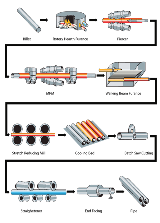
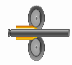
The use of Tubes to heat water started in earnest in the late 1800’s when the demand for pipes to supply water to urban centers and the steam locomotive railway industry was in boom. This coincided with the development of the Mannesmann Plug Mill Process with the use of Steel Billets to form seamless pipes along with a process called the Pilger rolling process.
The Tube, although might seem simplistic in its construct, is an end result of a highly complex process. Tubes are thus to define briefly a fluid transfer device that is specifically designed to account for heat transfer required as per application, which decides the following factors in tube selection:
- Tube Outer Diameter
- Tube Thickness or Inner Diameter
- Tube Material
- Tube Length
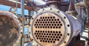
The Tubes are mounted on a plate called a tube sheet and this sheet can vary in thickness according to the application. Let us now understand a basic application using A Shell and Tube Heat Exchanger for example and understand the role of tubes in this type of process equipment.
Below is a common configuration of the shell and tube-type heat exchanger:
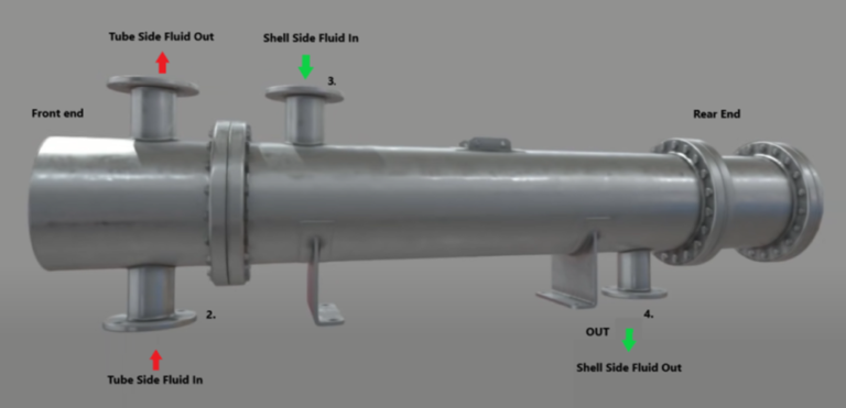
This type of heat exchanger can be broken down into the following major components:
- Shell
- Fluid Inlets and Outlets
- Tubes
- Baffles
- Tube Sheets
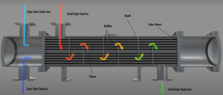
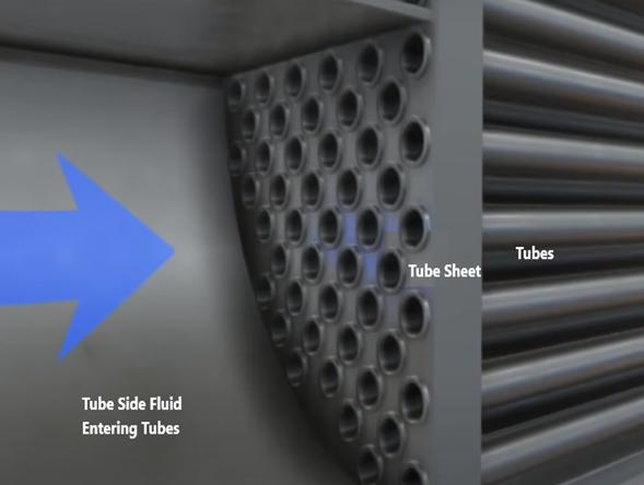
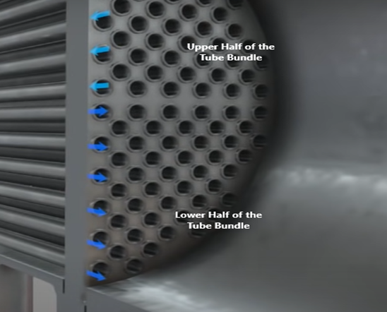
The Tube Side Fluids and the Shell Side Fluids are isolated from each other using the Tube Sheets. The Tubes in this particular heat exchanger are designed to allow two passes (multi-pass design) for the tube side fluid whilst exchanging heat from the shell side fluid (also a multi-pass design). The Tube Bundle is divided into two halves (Upper and Lower). The tube sheets act as pressure boundaries. The Baffles are arranged in such a way that the tubes pass through them and are supported along their length at regular intervals. The baffles also redirect most of the shell side fluid in a “zig-zag” pattern ensuring multiple passes, higher dwell time, and good contact with the external side of the tubes thus allowing sufficient heat exchange using turbulent flow. The Tube side fluid thus gains heat and the shell side fluid loses heat in this particular demonstration. TieRods are sometimes also used in the place of Baffles to support the tubes.
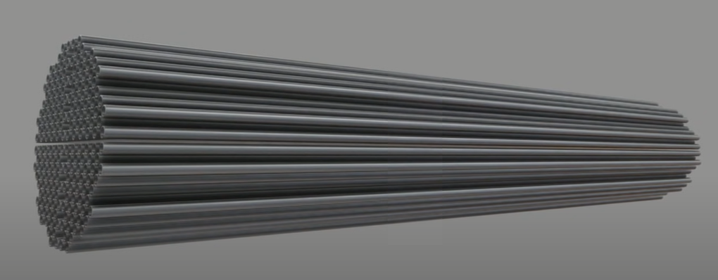
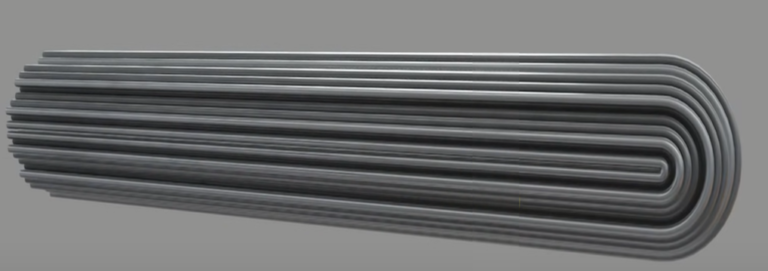
As mentioned earlier there are several types of designs when it comes to allowing a number of passes, type of fluid flow, and arrangement of tubes in a heat exchanger.
Below are a few examples of the different types of heat exchangers according to the number of passes, Type of fluid flow direction, and Arrangement of tubes
There are three main flow types, these are parallel, counter, and cross flow. Due to design considerations and the applications of heat exchangers, it is rare that a heat exchanger be only one of these flow types, usually, they are a combination of several flow types e.g. counter cross flow.
- A Cross Flow Heat Exchanger
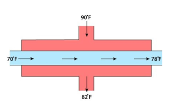
- Counter Flow Type Heat exchanger
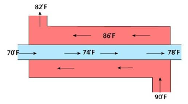
1) Single Pass Design:
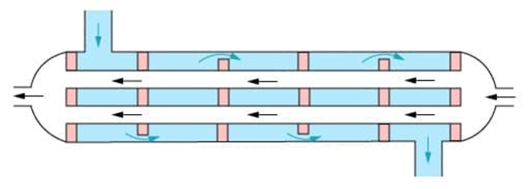
A simple difference between different types of Heat Exchangers is that they are known by different names according to their application viz., Boilers, Condensers, Evaporators, Chillers, Reboilers, Reheaters, Steam Generators, Fire Tube and Water Tube Boilers, etc.
But before we understand the tools, let us first understand some of the Process equipment where these tools are used.
In no particular Order,
- Boiler Feedwater Heater:
Feedwater is heated prior to it entering a steam generator or boiler. Extraction steam from the steam turbine(s) is used to heat the feedwater. In a feedwater heater, extraction steam is the shell-side fluid whilst feedwater is the tube-side fluid. As the steam transfers its heat to the feedwater, it condenses, and is drained out of the bottom of the heater; the drained fluid is referred to as ‘drips’. Note that a feedwater heater has a very similar design to a U-tube shell and tube heat exchanger.
2) Moisture Separator Reheater:
Moisture separator reheaters (MSRs) are installed after high-pressure or intermediate-pressure turbines; their purpose is to reheat cycle steam and remove cycle steam moisture.
3) Shell and Spiral Heat Exchanger:
This type of heat exchanger is not as popular as the plate type, and shell and tube type heat exchangers, but it has still found application in several industries. It is compact, can handle multiple phases e.g. steam and water, multiple fluids, and is suitable for a wide range of pressure and temperature applications.
4) Steam Turbine Condenser:
A steam condenser is a closed vessel-type heat exchanger applied to convert low-pressure exhaust steam from the turbine to water. A steam condenser is a mechanical device employed to condense the exhaust steam of the turbine into the water. It conducts this process with the help of cooling water that circulates inside it from the cooling tower. The pressure within a steam condenser is held below the atmospheric pressure to enhance efficiency. It is commonly used to lower the back pressure of the exhaust at the turbine end.
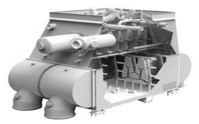
A Few Advantages and Disadvantages of Shell and Tube Heat Exchangers:
Advantages
- Cheaper in comparison with plate heat exchangers.
- Relatively simpler in design and are easier to maintain.
- Suitable for higher pressures and temperatures compared to plate heat exchangers.
- It is easier to find and isolate leaking tubes.
- Tubes can be ‘double walled’ to reduce the likelihood of the shell-side fluid leaking into the tube-side fluid (or vice versa).
- Do not foul as easily as plate heat exchangers.
Disadvantages
- Less efficient than plate heat exchangers.
- Require more space to open and remove tubes.
- Cooling capacity can not be increased, but a plate heat exchanger’s capacity can be increased.
Let us now study the processes and the tools involved in MRO operations of Heat Exchangers with Tube Tools and Accessories.
- Tube Installation
- Tube Removal
- Tube Cleaning
- Tube Installation: Before the Tube takes its place on the Tube Sheet, The Tube installation process has several steps to complete.
- Reaming: The Tube Sheets have tube holes which must be prepared to meet even the slightest manufacturing inconsistency. Thus the tube hole must be reamed to enlarge it and size according to the tool. Thus a tool such as a tube sheet reamer is necessary.

Grooving: In order to make sure that the Tube has an indent that can rest in the tube sheet, the tube sheet hole is grooved on the internal diameter so as to allow the expanded tube to sit firmly in the tube sheet. A grooving tool as shown below is used to carry out this task.


Expansion: The tube is expanded using expander tools to fit in the tube sheets. The tube rolls on the tube expanders push the tube walls and mold them against the tube sheet slowly yet firmly. Tube expanders are chosen as per the thickness of the tube, usually measured in Birmingham wire gauge. The internal and external diameter of the tube can also be used as the reference. The material of the tube decides its thickness while designing the heat exchanger. According to the access conditions, the expander tools length and the accessories that shall be used are decided.

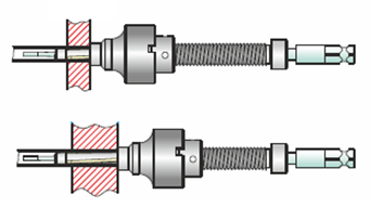
Tube Expander with a Pilot to guide it into the tube along with a square drive that can use Hydraulic, Pneumatic, and electrical drives to rotate and slowly expand the tube using this tool and the shaft that pushes the rolls outwards against the tube walls. The various tools and accessories allow the tube tool to navigate complex fabricated process equipment.
To broadly categorize tube expanders, there are two major types:
- Boiler Tube Expanders
- Heat Exchanger and Condenser Tube Expanders
Boiler tube expanders are designed to service thicker tubes with larger diameters in boilers that operate these process equipment at higher temperatures. Whereas heat exchanger and condenser tube expander tools are made for servicing tubes with lesser thickness and tube diameters and relatively lower temperatures. These are the two major tube expansion systems.

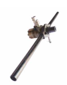
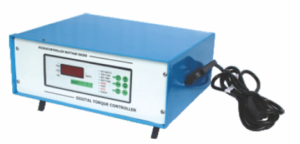

Hydraulic Tube Expander systems with its drive and electric tube expansion system with a wattage-based controller and a pneumatic drive system. Various Rolling Drives find application with heat exchanger tube expanders. Continuous Hydraulic tube expander systems are systems with flexible shafts that transfer spinning action to the tube expander,
- Tube End Facing: If the tube is found to be of excess length, then the end of the tube is reduced and the tube is right-sized using an End Facing tool. Tube end facing is done using cutting tools on specialized tools such as the one shown below.
Tube Flaring: Many Tube Rollers are also equipped with tube flaring rolls that assist with ‘folding’ the tube ends against the tube sheet. Below is an example of an expander tool with the flaring rolls integrated into the design.
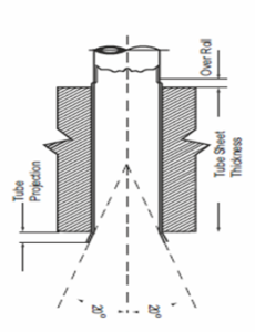


Flaring Tools are used aligned with chipping hammers to rapidly flare tubes
- Tube Guide and Tube Sheet Brush: Just before the tubes are installed the tube sheets are cleaned with a brush and the tube has a guide inserted into the end that shall go first and the protruding end guides the tube through the baffles.


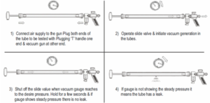
Tube to TubeSheet Leak Detection: The Tube that is now installed must be checked for leaks between the spaces of tube sheets and the tube itself. A complex device that can operate using a vacuum and detect even the slightest pressure drop. The below example uses this principle.
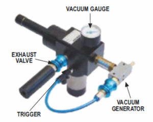


The tube seal inflates and plugs the gap in the tube, this allows the vacuum between the tube and tube sheet to be formed, if there exists a leak, then the pressure drop would allow its detection.
Tube Leak Detection: The Tube itself might develop leaks, it may be due to inadequate inspection during installation, manufacturing defects, damage during transportation or installation, improper operation of the process equipment, etc. To deduce the location of the leakage, the tube must be inspected using a tube leak detector.
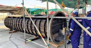
B) Tube Removal: Damaged tubes must be removed from the Tube Sheets, as they are a hazard to the functioning of the process equipment they are a part of. The Tubes can become inefficient or nonfunctional due to various factors ranging from sedimentation, and chemical attack causing pitting on the internal surface of the tubes which could even lead to minute fissures. This calls for an array of tools that can remove the tubes from the tube sheet.
Tube Collapsing Tools, Wall reducer, Drift Knockout Tools
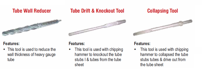
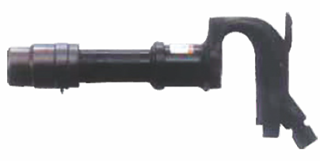
Pine Jenny style and manual tube pullers


The serrated edges allow the tube to be gripped by the tool which would later allow the tube to be pulled from the heat exchanger.
- Internal Tube Cutters

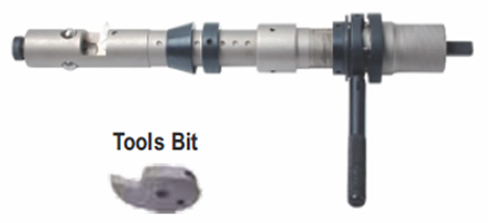

Tube Internal diameter cutters use a sharp cutting tool to shear the tube on the inside allowing the tube to be removed from the other end.
Tube Plugs

Tube plugs are designed to seal off leaky or damaged tubes in heat exchangers, condensers, boilers, etc. It Ensures a uniform joint without damaging the tube sheet. They come in two variants whether they are one piece or two piece.
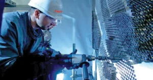
- Tube Pulling guns and various other means of tube pulling: Hydraulic Tube Pulling guns that use a reciprocating mechanism and use hydraulic pressure to draw out tubes once the tube has been cut on its internal diameter. The other accessories like spring balancers and impact wrenches are used to suspend the tube pulling guns and then grab the tube using the tube pullers if necessary. Once the tube puller is fixed in the tube the tube pulling operation can begin.
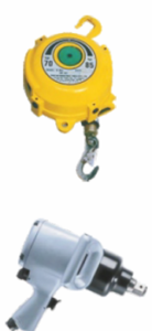
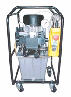
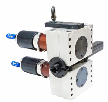
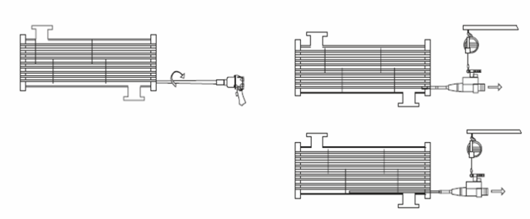
The hydraulic pumps and the hydraulic tube-pulling guns are other options for removing tubes using reciprocating tools. Continuous Hydraulic Tube Pulling Systems or hydraulic tube pullers are among such systems. Pneumatic motor-based gearing systems can remove tubes rapidly especially suited for thinner tubes.
- Weld Removal Tools: Another tool to remember before the tube pulling operation can begin is the weld removal tool, this removes the peripheral weld around the tube, allowing further processing of the tube with tube cutting, etc.

C) Tube Cleaning: It is uneconomical to use a tube only once, thus even a high wall thickness, high alloy tube would still require cleaning on a periodic basis, which would be contingent on the type of fluid that passes through it.
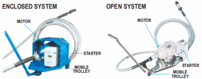
Tube Cleaners: Tube cleaners can use sources of power such as pneumatic and electric sources available in most plants that use heat exchangers. for example, electric Tube cleaners are environmentally friendly, compact, and easily maneuverable units used to clean straight and curved tubes in heat exchangers, condensers, boilers, and other tubular apparatus. They work by attaching a cleaning tool (to be determined by the type of deposit) to a flexible shaft. The electric Tube cleaner provides rotary motion to the flexible shaft which rotates the cleaning tool inside the tube. If needed water passes through the flexible shaft to aid in flushing out the deposits. Pneumatic Tube Cleaners also work in a similar manner except that they use pressurized air as the source of moving their prime mover. These platforms are equipped with a mobile trolley to help navigate around the process equipment.
Accessories and tools that are used with Tube Cleaners:
Flexible Shafts:
The flexible shafts are a sheathed tube with a steel cable that spins using a square drive. The flexible shaft is then connected to the tool end, which is used to clean the tube from inside.
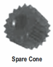
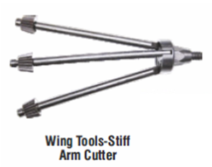
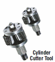
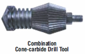
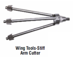
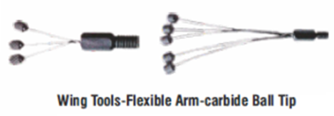
Cleaning Tools such as the ones below are used with flexible shafts. Depending on the density of the deposit, the cleaning tools are selected.


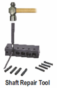
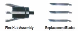
There are replacement and maintenance tools that are used to repair the flexible shafts and the cleaning tools
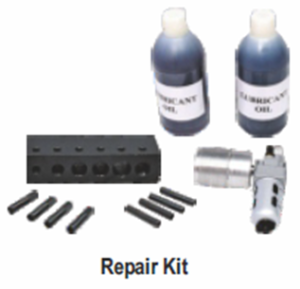
In addition to the larger tube cleaners, there are also portable versions of these machines
Various other cleaning accessories and consumables are used according to the type of sediment deposited in the tube.
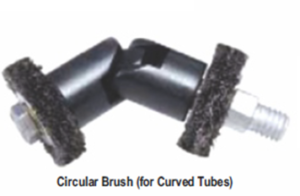
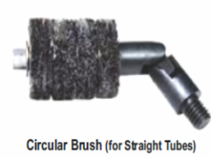
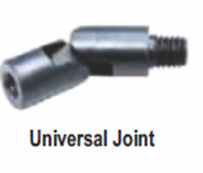

In addition, there are special cleaners for tubes in sugar mill plant heat exchangers and boilers. Brushes of various types and sizes are used with these machines to clean sugar mill tubes.
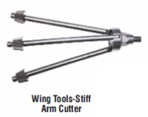
The necessity of the activity of cleaning tubes is learned when dropping efficiency, breakdowns, and accidents. To avoid lower efficiency and escalating costs it is necessary to set up a timely tube cleaning maintenance program. Below mentioned are a few consequences of avoiding maintenance and inspection activities in a timely manner.

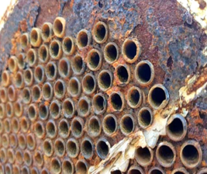
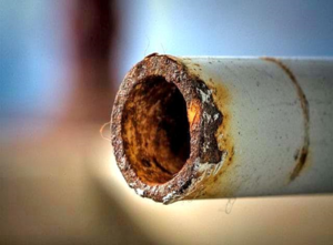
Conclusion:Considering the vast field that is maintenance, repair, and overhaul operations for heat exchangers, boilers, and condensers, it is difficult to accommodate an all-encompassing granular analysis of this field in one article. But to give an overview of this field was the objective of this article. To summarize we have covered the construct of the most common type of heat exchangers, and their various configurations of the same. We have also seen the various types of tools and equipment used during the tasks ranging from tube installation tools and tube expansion systems to tube pulling tools, etc.
The tubes are at the heart of the heat exchanger systems and other similar process equipment. It is necessary to take precautions and follow procedural correctness while installing, maintaining, repairing, and then if required discarding and replacing them in a timely manner. The mentioned equipment and tools are necessary for making a checklist for any plant operation specialist.
Leave a Reply