Since antiquity, Humans have used fasteners to hold components and objects together. They have evolved according to need and time. The modern bolt is a highly standardized and widely accepted engineering implement. These bolts must sustain several stresses and strains as mechanical members & as a part of structures and machines. They offer excellent advantages, such as a reliable temporary joint with some prudent flexibility that allows it to sustain shocks.
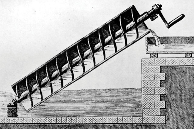
Archimedes Screw
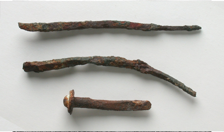
Archaeological digs regularly regurgitate metal nails and rivets
The Modern fastener is a merger of ideas
A Cylindrical rod with helical grooves or threading and hexagonal stoppers with internal helical grooves or threading to hold two objects while passing through a hole; is a mere simple description of the modern engineering marvel that is the mechanical bolt or stud. To specify, A stud has no fixed end but a bolt has a fixed end. Fasteners in general surround us in our lives.
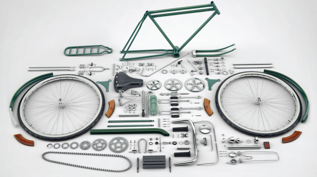
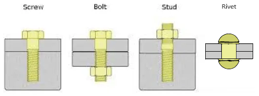
There is much to know about the ubiquitous fasteners that meld into our daily life.
Bolts must be fastened on the various surfaces and available spaces with the appropriate amount of torque or tension, depending on the application. A reliable tool can allow the operator to use little effort and time and remain safe while completing the task. There are multiple types of fasteners. But, we shall learn about all these topics going forward related to bolts in particular.
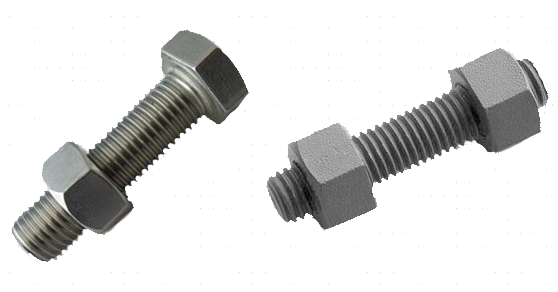
Bolts and Studs are the foundation of modern industries
Categorization of Bolted Joints:
Bolted joints could be classified into three major categories according to application. For convenience, broad classifications are made under these umbrella terms.
- Process Equipment and Piping-related joints: It is a joint generally consisting of a gasket or seal, and covering or connecting two or more vessels or pipes with Flanges that are bolted together would be classified under this section. These joints require occasional removal and retightening for purposes of maintenance, overhaul, or repair of the said pipe or process equipment. E.g.: Oil and Gas Production Industry.
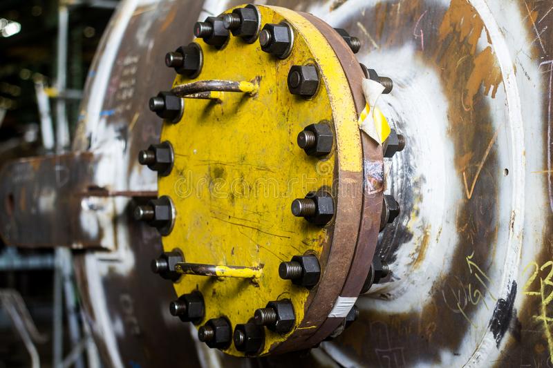
- Machinery Joints: It is a joint that is made on static or dynamic components of machinery or vehicles and generally has direct metal-to-metal contact. This type of joint requires frequent opening and closing due to inspection, and maintenance requirements. E.g.: Powerplant Machinery.

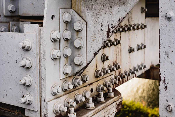
- Structural Joints: Meant for all types of bolted structures, buildings, and bridges. It is a joint that also has direct metal-to-metal contact but generally does not require opening and closing of the joints until there is an urgent requirement for refurbishing for safety purposes, relocation, overhaul, or demolition.
A Dynamic System:
Although a bolted joint might look static, it has several forces acting on it and it too exerts its own forces on the joints it holds together.
A bolt offers certain unique advantages such as the following:
- A Bolt is removable and can be reused several times without using much of its original strength and properties.
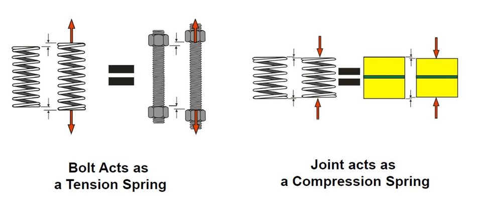
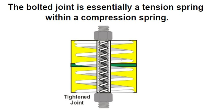
- A Bolt holds joints together under tension and exerts clamping force on the joint. This ensures that the bolt shall continually expand/stretch (like a tension spring) and the joint shall always contract (akin to a compression spring).
- Bolts act like springs thus they can sustain forces/pressures trying to overcome the clamping force and hold the joint together.
To elaborate further,
The force that the bolts exert on the joint is called a ‘clamping force’. A clamping force is also called a preload. total preload must be greater than the pressure trying to push the joint apart.
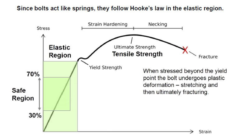
Since a bolt is akin to a compression spring, it shall have the Hook’s Law applied to it as well. Which says that the Force and elongation/stretch are directly proportional within the elastic limit of the material.
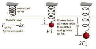
Every material has a certain yield strength, beyond which the material shall cross its elastic limit and cannot retain its original shape. It shall have thus entered its plastic range and the deformation/elongation shall be permanent. Additionally, if the material crosses this Plastic range it shall suffer from necking and fracture/buckle under the load.
A bolted Joint is thus a Tension Spring within a Compression Spring. Thus we need enough spring action to Clamp the joint together but not too much so that the bolt yields and no longer springs back.
For Bolting purposes, we generally limit the usage of bolts within a ‘safe region’ of 30% to 70% of their yield strength, allowing some safety margin to compensate for environmental factors and material properties. This varies according to applications, to speak of examples
- Pipeline Flange-based joints: 40 to 50 % of the Yield Strength – This limitation aims to ensure that the gaskets usually present in these joints are used optimally and are not crushed by the Pipe flanges.
- Machinery Joints: 65 to 70 % of the Yield Strength – This limit is due to the frequency of the tightening and loosening of the bolts.
- Structural Joints: 85 to 90 % of the Yield Strength – Here, the bolts are rarely unfastened thus they can be tightened to the maximum considering only a marginal safety factor.
To tighten bolts to the optimum value we must have a datum to refer to, thus the need for standardization. This has produced three commonly used and accepted standards for bolt manufacturing amongst many. Standard fasteners are specified by various organizations. These fasteners are typically specified according to their yield strength.
SAE – Society of Automotive Engineers (Section – J429)
ASTM – American Society of Testing Materials (Section – A193)
ISO – International Standard Organization (Section – 898)
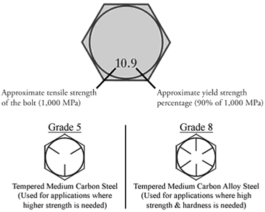
An ISO 10.9 Grade bolt has a marking on the face of the bolt with a number that designates the maximum tensile strength and the approximate yield strength. While one can know about the SAE grade of the bolt according to the number of markings on the face of the bolt and add 2 to it.
This gives us a reference as to the applicable limits of the bolts.
There are two primary methods of stretching a bolt, viz.,
- Torqueing
- Tensioning:
- Hydraulic
- Mechanical
- Induction Heating
Torqueing method:
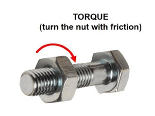
It can be defined as Turning the nut with friction
Threaded fasteners have screw threads in the form of an inclined plane. As the bolt turns in the nut it creates a mechanical advantage capable of high forces. Applying torque is the most common method of controlling the tightening process.

Torque is the force multiplied by the distance or length of the lever arm.
Torquing force can be calculated using the following formulae,
Torque = Force X Length
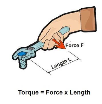
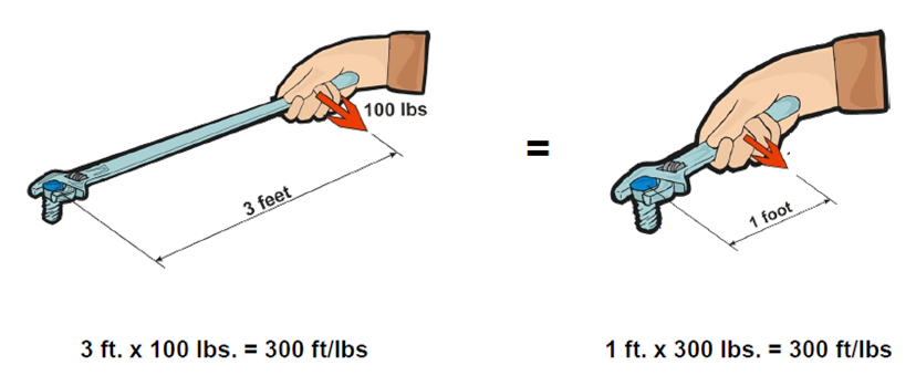
E.g.: Torque = 100 X 1 = 100 Ft. Lbs.
Metric units for torque will be measured in Newton Meters (Nm).
One may increase torque by increasing the lever arm length or increasing the applied force
Torque = K X D X F / 1000 = Nm or K X D X F /12 = Ft. Lbs.
D – Diameter of the Bolt
F – Force
K – Coefficient of Friction
For Torque Tools, there are several ways of classifying them. One method is according to the source of power:
- Manual – Click (link), Dial, Electronic Manual Torque Wrenches
- Electric (link)
- Pneumatic (link)
- Hydraulic (link)
Classifying Bolting according to the degree of torque control leads to three classifications:
- Uncontrolled Bolting – There is no measure nor control of the amount of Torque Being applied
Eg.: Spanner or Hammer

- Partially Controlled Bolting – There is control of input but we cannot control or predict the exact output due to a lack of a feedback mechanism or information for the exact elongation in the bolt.
Eg.: Hydraulic Torque Wrenches, Pneumatic Torque Wrenches, Electric Torque Wrenches, etc.
- Fully Controlled Bolting: There is a control of input and it is informed by the feedback from devices such as Ultrasonic bolt tension monitors
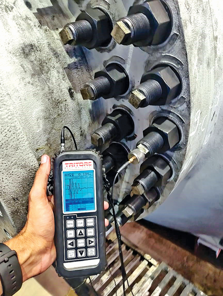
Eg.: Hydraulic Torque Wrenches (link), Pneumatic Torque Wrenches (link), Electric Torque Wrenches (link), etc. in combination with Ultrasonic bolt tension monitors. (link)
It is certain that all torque tools depend on the same principle of Action & Reaction which can be more accurately defined by Newton’s Third Law of Linear Motion: Every Action has an Equal and Opposite Reaction.
By giving a basic derivation of this law we can say that,
Newton’s Third Law of Rotation: For Every Applied Torque, there is an equal and opposite reaction torque.
The application of torque by the driver generates an equal and opposite torque on the tool which must be braced with a reaction arm.
Using conventional torque tightening, extremely high reaction forces impact the equipment. These reaction forces can be extremely hazardous and even damage equipment.
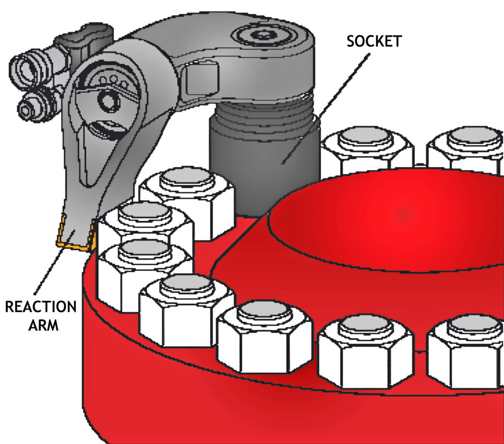
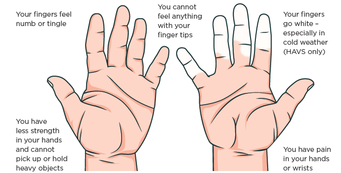
Tools that do not distribute reaction forces into a reaction surface, usually end up transferring these forces into the hands of the user. Eg.: Impact Wrenches – cause Hand Arm Vibration Syndrome.
To elaborate on the earlier mentioned K factor in the torque formula,
Friction is the force resisting the motion of solid surfaces sliding against one another. Friction arises from surface imperfections as surfaces move against each other.
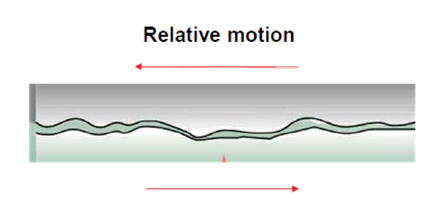
Friction is the main factor for the loss of most of the torque energy used to tighten a bolt. An estimated 90% of this torquing input energy is lost overcoming friction.
The usual locations and surfaces are usually situated under the head of the bolt, nut, and threads. Barely 10% of the input energy is converted to bolt stretch/elongation.
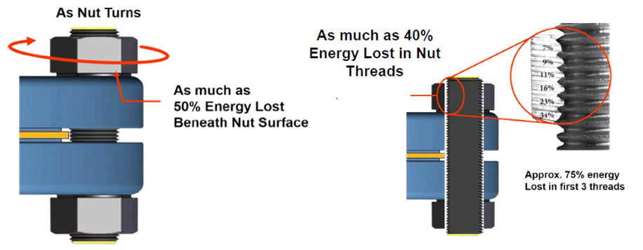
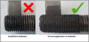
Because of this, lubrication of the bolt is necessary to ensure that the least amount of torque is required.
Generally, once the fasteners are lubricated nearly three times less torque is required. Although, one must ensure that the lubrication is applied to both the bolt threads and the nut face.
General description and modus operandi for Hydraulic torque wrenches:
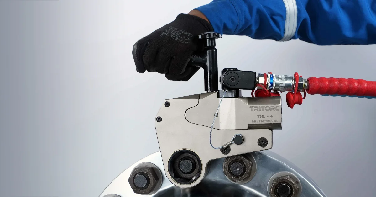
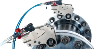
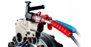
Hydraulic Torque Wrenches are a ubiquitous workhorse of the bolting world. They can provide predictable torqueing for long operations. They come in various bolt sizes and can work irrespective of thread profiles. They have two major variants viz.: Low Profile or Ratchet type (link) and Square Drive type (link). The modern hydraulic wrench uses features such as a swiveling hydraulic manifold, self-ratcheting drives, narrow nose radii, and a light weight body amongst many other advantages.
Hydraulic Torque Wrenches Front View Show the advantages of using the Low Profile Torque Wrench in constricted Spaces
360⁰ X 180⁰ freedom of movement for the Swiveling Hydraulic Ports.
This tool requires a Powerpack/ Hydraulic pump to push a cylinder to move a drive which rotates/torques the bolt. The square drive is mounted with a socket that fits over a bolt. Usually a backup wrench is used to brace the nut from behind for a successful torquing operation.
Detachable Reaction Arm, Sliding Square Drive, Laser Engraved Torque Chart allow easy reference and flexibility to reach reaction surfaces for both tightening and loosening operations.
Operation for Bolt Tightening and Loosening:
Attachment of the desired Socket to the Square Drive
Connection of the Hydraulic Hoses to the Swivel hydraulic hose connector
Connection f the hoses to the pump unit
- First, the size of the bolt to be tightened is identified and the appropriate socket is chosen to fit it according to the space available.
- The high-pressure hoses are attached to the Square Drive Hydraulic Torque Wrench and the Pump Unit.
- The flange to be tightened has the bolt holes numbered according to ‘star pattern’ bolting to ensure uniform compression of the flange.
- Initiate torquing whilst keeping a back up wrench or slugging wrench to brace the nut of the stud or bolt from behind.
- Since the reaction arm is removable and the square drive can slide to other end of the tool, the torque wrench can be used to initiate the loosening of the bolt after a few adjustments.
A standard addition to one’s tool kit consisting of torque wrenches and other bolting tools
Tensioning method:
It involves Pulling or tensioning the bolt and then turning the nut without friction.
- Hydraulic Tensioning:
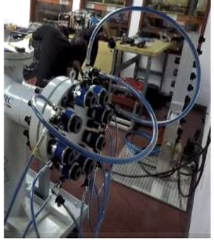
In this method, a hydraulic bolt tensioner tool (link) is used on the bolt. It generally has the following basic components

- Thread Puller (Marked Yellow): A special type of nut that engages the stud and stretches the stud.
- Hydraulic Cylinder & Piston (Marked Blue): Cylinder Body & Piston that lifts the puller when hydraulic pressure is applied.
- Bridge & Socket (Marked Cyan): A Platform that allows access to tighten or loosen the nut while the cylinder is under pressure, retaining the bolt tension.
The steps to operate a bolt tensioner include the following:
- Attach the Stud
- Apply hydraulic pressure to the tensioner stretching the stud.
- Tighten/turn the nut against the flange to hold the stretch.
- Release pressure and remove the tool.
There are several types of Tensioners some of them are as follows:
- Multi-stage Tensioners: These tensioners have a smaller diameter and have multiple pistons to make sure that the bolts can be tensioned simultaneously by the multiple pistons with greater force that would otherwise not be possible in a small space.
- Sub Sea Tensioners: As critical infrastructure on seabed-based structures increases the need to maintain these structures also gains priority. Thus these corrosion-resistant Tensioners with a split clamp are used to quickly latch onto the bolts on flanges of pipes to speak of an example. There is limited time due to safety concerns for the scuba divers and the underwater Remotely operated vehicles are costly to operate on an hourly basis, thus speed of operation is a top priority for these applications.
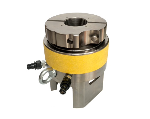
- Spring Return Tensioners: An increasingly common feature in all hydraulic bolt tensioners, the use of the spring return mechanism for the load cell piston ensures that the operator does not have to manually lower the piston or puller bar using a tommy bar. Thus he can move onto the next bolt quickly and this reduces setup time or downtime.
2) Manual Tensioning:
Without the use of any hydraulic or pneumatic power source, manual tensioning depends on using devices such as the Jackbolt.
here the radially arranged bolts are tightened in a diametrically opposite fashion, which leads a puller cylinder to tension the bolts.
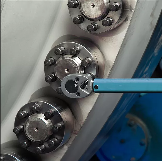
3) Induction Heating:
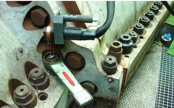
Here, We heat the bolt to a certain temperature through an induction heater. This expands and elongates the bolt and allows the rotation of the nut. We rotate the nut by using a slugging wrench/spanner. But it is necessary to allow the bolt to cool down and thus achieve clamp force.
A special section for pressurized joints:
Bolting has critical applications for pressurized joints related to pipes and process equipment.
A Flange is an effective and proven mechanical member of a piping system. Its primary function is to allow access for inspection, cleaning, maintenance, repair, and even modification of the system. These are either welded or screwed into the primary piping system. Operators fasten Flanged joints by bolting together two flanges with a gasket to provide a seal.
Several Flange types are used primarily in the Petrochemical and Chemical Industry Some of them are:- Welding neck flange, Slip-on flange, Socket Weld Flange, Lap joint flange, Threaded Flange, and Blinded Flange. Manufacturers make these flanges using stainless steel, cast iron, aluminum, brass, bronze, plastic, etc., but the most used material is forged carbon steel and has machined surfaces.
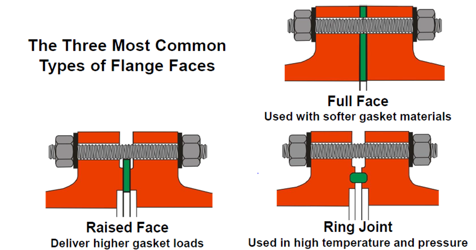
There are gaskets that are used to ensure a proper joint between two flanges. According to the application, the flange faces have variants that find utility, here are some types of flange face types.
- Full Face Flanges: Used with softer gasket materials.
- Raised Face Flanges: Designed to deliver higher gasket loads.
- Ring Joint Flanges: Used in high-temperature and pressure applications.
Flange Alignment:
Pipe alignment, especially for large-diameter pipes is a multispectral challenge, of which bolting is one aspect. These defects cannot be corrected by bolting alone.
To generalize bolting relevant pipe misalignment types there are two:
- Lateral Misalignment
- Radial Misalignment

Gaskets:
To compensate for minor machining errors, gaskets are used. They are available in various sizes and forms according to their application., to name a few.
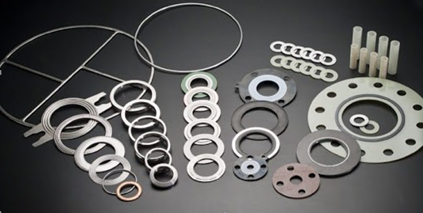
- Metallic Gaskets
- Spiral Wound Gaskets
- PTFE (Teflon) Sheet & Molded Gaskets
- Compressed Non-Asbestos Fibre Sheet
- Premium Grade Rubber Sheet.
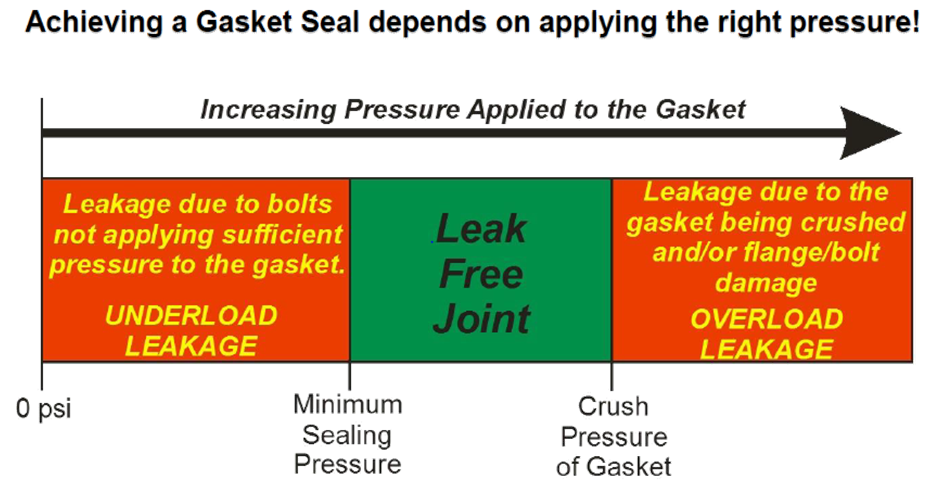
To achieve a Gasket Seal depends on applying the right pressure.
Parallel Joint Closure:
In most bolted connections, what you do to one bolt affects the other, thus making them interdependent.
Interdependent bolts must be tightened in a sequence (pattern) and gradually (in steps/passes) – It would be similar to the method applied to tighten bolts on a car tire.
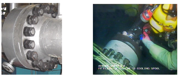
Many bolts are arranged in circular patterns, thus making it necessary to use a star-like pattern to tighten the bolts. The same pattern must be followed for multiple passes, usually, four passes with an increasing amount of load.
- Pass 1 – 20 % to 30 % – (cross pattern) align, close gaps, seat gaskets.
- Pass 2 – 50 % to 60 % – (cross pattern) apply incremental load
- Pass 3 – 100 % (cross pattern) achieve target load
- Check Pass (Dog Pass) – (circular pattern) check pass, even out load.
Single tool Bolting plan:
- Number of Bolts in a sequence
- Apply the torque in steps
- Check the results
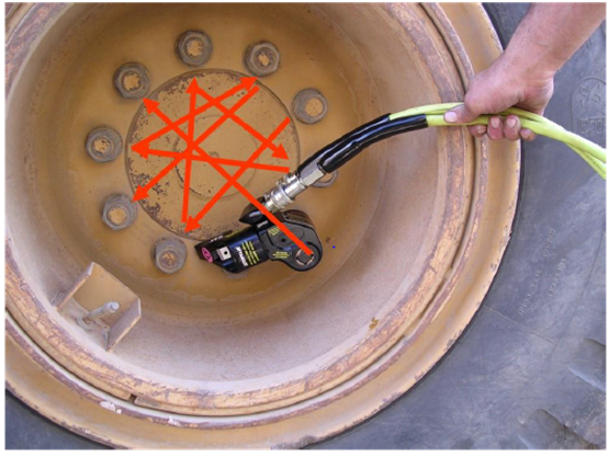
- “Plus 4” method:
- The approved method in ASME PCC-1
- Number the bolt at the 12:00 position as 1, 6:00 as 2, 3:00 as 3, and 9:00 as 4.
- Start at bolt 1, go clockwise, and add 4 to the number of the previous bolt, starting again when you reach the bolts you have already numbered.
- This pattern will work for all circular bolting layouts.
Certain precautions that one must keep in mind while operating these tools:
- Wear PPE (Personnel Protective Equipment)
- Head Protection: Safety Helmet
- Eye Protection: Safety Glasses
- Hearing Protection: Earplugs
- Protective Clothing: Boiler suit, Safety harness (if working on height)
- Hand Protection: Gloves
- Foot Protection: Safety Shoes
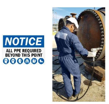
- Avoid Pinch Points:
- Caution with Reaction Forces
- Avoid Reaction Arm, Pinch Hazard
- Avoid Backup Wrench Pinch Hazard
- Avoid Line of Fire:
Hydraulic Tensioning involves high-pressure hydraulic fluid, up to 30,000 psi.
- Take caution with hydraulic pumps and hoses.
- Avoid the line of tensioner fire.
Disclaimer:
Tritorc does not wish to infringe upon any copyrights related to the products, services, or images used in this article.
Leave a Reply